Jump to content

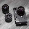
What's the true story surrounding the birth of Red Scale Elmars?


Recommended Posts

Advertisement (gone after registration)

In those years, the best way to perform the long and iterative computations for lens design, mostly centered on trigonometric/logaritmic functions , was probably to use electro/mechanical scientific calculators, that were not programmable but fast, reliable, and at a price that allowed a Company like Leitz to buy 10/12 or so for the optical computing department people (they were "desktop devices" and several Germany / made existed at those times: Triumph, Walther, Diehl... and italian Olivetti, too)


Not to forget the "bombs" of the Polish (and later the English) secret service to decode the Enigma.


Jan

Edited by jankap
Link to post
Share on other sites

The noise of 10 comptometers running in a room must have been phenomenal. My father had just one comptometer running in his general office. The other ladies complained so much that after the first week, he had to have a sound proof booth with double glazing built for the comptometer operator. As I recall it, she was already deaf so it did not worry her greatly, she just turned off her hearing aids. They were very sophisticated machines. My father's one had about a 30 inch wide carriage for double wide accounting paper. You could set up the printing so that there were quick access buttons to various sections of the paper. In addition it had a number separate registers/totalisers to hold different running totals (mechanical memories), which was complicated by using non-decimal pounds, shillings and pence. It looked something like the one below. The operators were very well paid, which I recall my father telling me, caused some ill feeling in the general office. 


Wilson


Welcome, dear visitor! As registered member you'd see an image here…

Simply register for free here – We are always happy to welcome new members!

  • Like 3
Link to post
Share on other sites

.... The redesign of the Elmar may be computed with elector-mechanical machines like http://www.rechnerlexikon.de/artikel/Mercedes

WOW !! Thanks for the link... shouldnt'i collect the items we are speaking of (lenses... :) ) I'd like a lot to put ensemble a collection of mech/electromech computing devices... they were fascinating (just an example...https://en.wikipedia.org/wiki/Curta )


I have had a pair of Brunsviga (https://en.wikipedia.org/wiki/Odhner_Arithmometer), a Triumph, an Olivetti (mytical "Divisumma"... 30 sec for a complex 8 digits division...) but then sold them away...

Edited by luigi bertolotti
Link to post
Share on other sites

I asked about the optical designer in charge because it seems with the Red Scale Elmar Berek's lens design was kept in mind: a lens with zero distortion, and very good through all its range, while with the next step Leitz took soon after that, making the Elmar an f/2.8 lens, and then designing a really new f/2 one (Summicron) the design team at Leitz look like having started, slowly first (2.8), the new direction the firm then followed for decades: faster lenses, able to focus closer, with higher sharpness reaching frame corners, at the price of some distortion present in several of their lenses... I imagine (not sure) the new direction was mainly Mandler's idea, so I was thinking if another designer did the last 3.5 recomputing...  But I've also read Mandler and Berek both worked at Leitz during a few years, and sometimes Mandler is said to have worked "with" Berek...  About barrel and pincushion distortion, people's opinions differ...  Personally it disturbs me when it can be seen in the picture: I feel the rendering of lenses without distortion, like Elmars and Summarons, is something that in a natural way helps me going into the image and feeling it real, because a lens without distortion sees the way our eyes see reality... I think, and feel, that's a lot more important than sharper frame corners with the lens wide open, or focusing closer to our noses...

Edited by Juan Valdenebro
Link to post
Share on other sites

I asked about the optical designer in charge because it seems with the Red Scale Elmar Berek's lens design was kept in mind: a lens with zero distortion, and very good through all its range, while with the next step Leitz took soon after that, making the Elmar an f/2.8 lens, and then designing a really new f/2 one (Summicron) the design team at Leitz look like having started, slowly first (2.8), the new direction the firm then followed for decades: faster lenses, able to focus closer, with higher sharpness reaching frame corners, at the price of some distortion present in several of their lenses... I imagine (not sure) the new direction was mainly Mandler's idea, so I was thinking if another designer did the last 3.5 recomputing...  But I've also read Mandler and Berek both worked at Leitz during a few years, and sometimes Mandler is said to have worked "with" Berek...  About barrel and pincushion distortion, people's opinions differ...  Personally it disturbs me when it can be seen in the picture: I feel the rendering of lenses without distortion, like Elmars and Summarons, is something that in a natural way helps me going into the image and feeling it real, because a lens without distortion sees the way our eyes see reality... I think, and feel, that's a lot more important than sharper frame corners with the lens wide open, or focusing closer to our noses...


As someone who has had a number of eye operations I cannot truly judge what distortion exists in a photograph. I do know, however, that I have rarely observed any distortion, even with my poor sight, in any photo taken with the classic 50mm/5cm Elmar lens. As I said before, I have observed only a slight improvement with the Red Scale Elmars, but nothing like the big step forward with the Summicrons.


The big issue here is whether the improvements in the 1950s were due to men or machines. The answer is probably both. The development of lens design really took off after the dawn of photography in the 19th Century. It has continued progressively ever since then and today's lens designers have the benefit of a great deal of previous research and experience as well as the possibility of very fine tolerances/adjustments due to modern technology. For anyone interested in the progressive development of lens design since the beginning of photography I can recommend the following two publications:


https://www.amazon.com/History-Photographic-Lens-Rudolf-Kingslake/dp/0124086403/ref=pd_sim_14_2?_encoding=UTF8&psc=1&refRID=0QVBHZD01GNW0FFZHW52


(Or several other technical publications by Mr Kingslake; this one, however, gives the best overview)


The publication below goes through individual lens manufacturers, including Leica, and indicates how lens design progressed in the 19th and 20th Centuries.


http://www.antiquecameras.net/lensvademecum.html


I know there are books specifically about Leica lenses ( eg Puts etc), but Leica lens design did not exist in a vacuum and others, coming from way before Leica existed, set out the grounds on which Berek and Mandler etc operated.


William

Edited by willeica
  • Like 2
Link to post
Share on other sites

back to RS... checking my Elmars I found yet another one which in theory should not exist - RS triangle with f16. Has no SN and shorter barell (comes with IA converted to IIasync mid fifities)

Welcome, dear visitor! As registered member you'd see an image here…

Simply register for free here – We are always happy to welcome new members!


and back to Luigi question about rotation f16/18/22. Upper picture shows lens inner barell with aperture ring. Ring is fixed with 2 screws, which rotate within the cutout (lower picture), cutout limits the rotation. Within cutout you may see another ring which holds aperture blades, this one rotates with the rotation of aperture ring.

  • Like 3
Link to post
Share on other sites

Advertisement (gone after registration)

Thanks Jerzy. As ever, you come up with great information. The lens on a I Model A would have had a smallest aperture of f18. So the lens head here would have been from a 1940s lens and it seems that this was then attached to a Red Scale mount with a triangle from 1953 or later. 


I have never seen an Elmar stripped down like this to show the screws which limit the rotation. I presume that the screw positions cannot be changed. Does this mean that a lens with a minimum aperture size of f16 cannot be subsequently changed to give either f18 or f22?


William

Edited by willeica
Link to post
Share on other sites


I have never seen an Elmar stripped down like this to show the screws which limit the rotation. I presume that the screw positions cannot be changed. Does this mean that a lens with a minimum aperture size of f16 cannot be subsequently changed to give either f18 or f22?


William

the lens shown on both lower fotos is not the RS, it is just one which I am cleaning now. I suppose you can change f16 to f18 and f22 by filing out the cutout on one side (there are two cutouts on both sides) however you would need to replace 2 other elements - front ring and either DOF ring or mounting ring depending where the DOF scale is engraved. It is clear I believe that in order to do so you will need to take the inner barell apart removing optics and aperture blades. No, position of the screws cannot be changed

  • Like 1
Link to post
Share on other sites

Hi,

After four pages of kind information from forum members, I’d like to offer future readers the  complete short answer I was looking for:  one that’s good just for uninformed forum members: I’m no expert and I’m just trying to practice my English and share information, so this is my view, and perhaps a romantic one, not an absolute…  Thanks everyone !!!

After producing for twenty-five years the lens that made the Leica name famous worldwide, the 50mm f/3.5 collapsible Elmar lens was recomputed at Leitz in 1951, two years after its designer Max Berek had passed away. 

Max Berek’s (and Oscar Barnack’s original) concept for the very first LEItzCAmera (then called miniature camera) was designing the smallest, sharpest lens without any distortion, and a very good lens through all its range: that lens design concept was truly respected when the type of glass and the optical formula were improved.   Minimum focusing distance, maximum aperture and optical design remained the same, while newer glass and small changes in elements’ curvatures and spacing improved performance by a small margin (older elmars were already great lenses) and produced a slightly larger sharpness circle and smaller softened frame corners’ areas.  

The recomputing was done during the few years when lens design wasn’t a totally optical/human process anymore, but neither a computer based one: Midland and Mandler’s computer aided design work would be known only a few years later, but hoping for a shorter minimum focusing distance or for the highest sharpness paying some distortion as a price, were not part of the new recomputed Red Scale Elmar recipe from 1951: the red scale Elmar was a true Elmar, and for its recalculation both extensive visual testing and comptometers (very noisy desk sized electromechanical scientific calculators for trigonometric and logarithmic functions) were heavily used.   After the Red Scale f/3.5 production, came the f/2.8 Elmar, a different lens, and one that showed a new design path in part shared with the Summicron and the rest of the more modern Leica lenses: the Red Scale Elmar f/3.5 was the last one of its kind.

During the early 1950’s the new 50mm f/3.5 Red Scale Elmar was available first in screwmount version, and then very soon in M mount…  It was produced from 1951 to 1962, so the whole Elmar f/3.5 production had an impressive life of thirty-six years that started in 1926, one of the longest production periods for any Leica lens.  There are two types of Red Scale Elmars: those made during the first three years of its production (1951-1953), just before the M-mount was offered, and those made from then on (1953-1962)…  The first ones, with serial numbers around one million, are called “diamond” red scale elmars because there’s a diamond or rhombus figure to mark the focused distance, while the second period ones share the same optical formula and performance but are called “triangle” red scale elmars because there’s a triangle, instead of the diamond, marking the precise focused distance…  It seems the change from diamond to triangle had to do with a change in the type of available glass, although performance is equal.

It was common back then at Leitz factory, upgrading cameras and lenses: many photographers sent their cameras to have them upgraded by Leitz technicians for flash use, and also sent their pre world war II lenses to have them coated, both for improved contrast in black and white and for better saturation with color film.  For this reason, coating service, there are some red scale elmars which have old elmars’optical cells inside, instead of real red scale elmars’ glass and formula: to avoid confusion, those upgraded older lenses inside red scale elmar’s metal housings have no serial number, or keep the original lens serial number, while true red scale elmars have official serial numbers for the 1950’s: close to one million and above.

Now in 2017, we can say the lens was designed a century ago…  It was sold from 1926 on, but it was indeed designed several years before that: Leica prototypes start in 1915-16.  The most amazing fact is, both optical quality and build quality were superb, and these days, the lens keeps performing amazingly well in the hands of a skilled photographer, on film cameras and also on digital cameras… 

This is the story of the small lens that changed photography forever, making it a portable hobby, and an invaluable witness in the documenting of our lives.

  • Like 3
  • Thanks 1
Link to post
Share on other sites

Your summary covers most of the main aspects discussed here. Some 'upgrades' were done by private technicians rather than by Leica, but with a very good technician it can be difficult to tell the difference. In addition to the two Elmars which I have that were converted by Leica from 11 O'Clock to 7 O'Clock and standardised, I have a late 1930s Summar with the mount of one variant and the head of another one. I cannot tell if this was done by Leica or by a private technician. I suspect it was the latter, but it works perfectly anyway and it is just as good as the other 10 examples of the Summar in my collection. If you really want to see variations of the Elmar over a short period of time you need to get a copy of Angela von Einem's book (in German only) on the variants of the I Model A with Elmar. You will be surprised at how many changes were made to the physical design of this lens in its very early years. Van Hasbroeck lists 22 variants of the Elmar, but I suspect that there are more.


William

  • Like 1
Link to post
Share on other sites

Hi,

After four pages of kind information from forum members, I’d like to offer future readers the  complete short answer I was looking for... .....


Now in 2017, we can say the lens was designed a century ago…  It was sold from 1926 on, but it was indeed designed several years before that: Leica prototypes start in 1915-16.  ....


Very good resume, Juan... but pay attention to the last sentence I quote here over : indeed, the Leica prototypes had NOT an Elmar.... (and, strictly speaking, neither a 50mm lens... the story of prewar Leica prototype(s) and its lens(es) can be found in several publications)


The ELMAR in itself is a "recent" design... probably on the drawing table of Max Berek in 1924 or even 1925... in fact :


- First Leica announced and sold had a 50mm Leitz Anastigmat lens - FIVE glass elements

- Soon after, the SAME lens was renamed ELMAX (E rnst L eitz MAX Berek), because photo lenses named "Anastigmat" were already in the market

- In 1925 the Elmax was replaced by Elmar : FOUR glass elements.


This is the basic story... (see http://www.marcocavina.com/articoli_fotografici/50mm_Leica_a_telemetro/00_pag.htm , for example) : rumors exist that the Elmar was a design VERY similar to the Zeiss Tessar ("Tessara" : "Four" in Greek.. four elements...) ... maybe a bit too much similar... but the Zeiss patent for Tessar expired just around the time that Leitz made the Elmar (this is a story that some experts have surely analyzed in depth...) 

Edited by luigi bertolotti
  • Like 2
Link to post
Share on other sites

Thanks Luigi. Within the first type of Elmar listed by Marco Cavino, there are several variations, some of which are mentioned by von Einem, including but not limited to the following from the years 1926 to 1931:


Curved front ring

Sharp front ring

Mount thread with/without cutout

Coarse or fine knurling

Letters engraved or stamped

No 7 metre marking on flange of very early lenses

Cutout for distance marks 6.5, 9.5 m

Light baffles within the barrel

Coarse or fine filter thread


Some of these are quite difficult to spot, but I have detected some of them in my collection.


William

  • Like 1
Link to post
Share on other sites

There was a rumour that Leica were given the alternative of paying a Tessar licence fee to Zeiss for the Elmar or agreeing to buy all their lens blanks from Schott. Any truth in this rumour or was it just something put about by jealous Zeiss lens owners? 


Wilson

Link to post
Share on other sites

There was a rumour that Leica were given the alternative of paying a Tessar licence fee to Zeiss for the Elmar or agreeing to buy all their lens blanks from Schott. Any truth in this rumour or was it just something put about by jealous Zeiss lens owners? 


Wilson


From the Lens Vademecum which I mentioned in a post above. I am not sure if all of this is correct, but it covers the copyright and glass type issues:


 The layout of this famous lens was roughly Q15 but the initial patent covers a lens with a front glass designed

so that the fundemental rays cut the axis near the front lens. (D.R.P. 343,086/1920). This led to a preferred iris

position nearer the front than usual, and it is between glasses 1 and 2 in most Elmar 50mm lenses, and to a

less curved interface in the rear element. The detailed design seems never to have been fully realized

commercially, as it featured a movable second glass to allow for correction of astigmatism in close-up, and

perhaps since the external glasses were of rather soft DBC. The next development was a 5-glass type, which

would not have fallen within the patents of the Q15 type and which may have eased the glass requirements.

Finally a glass from the Sendlingen plant of Goerz allowed the design of a Q15 type lens of f3.5 aperture

covering the whole of the 24x36mm frame. This was a new standard in 1925, and may have used features

from the above patent. It has been suggested that when Zeiss produced the f3.5 Tessar, the patent position

was sufficiently balanced for the firms to act independantly but without complaining if there was a possible

overlap.

The Elmar designer was Dr Berek, and the lens had to be heavily modified about 1929 as the Sendlingen plant

was then converted to produce other products and all optical supplies were taken from Schott. (The change

followed the unification of Zeiss Ikon in 1926.) As a result, the new type has a visibly flatter front curve, and

came into use about the time when the Leica Standard was introduced. Note that the iris position was kept in

the same place in the new model, except when these are mounted in blade shutters for the small number sold

in Compurs essentially for the Leica, Vollenda and Pupille cameras. These show the impressive covering

power of the Elmar since in the rollfilm versions it is covering 3x4cm and still works well.

Many years later, Leitz were to redesign it again with "new rare earth" glass and show the change as the new

red scale version. It is worth noting that the 'old' Q15 type did involve some compromise in the colour

correction, less serious in the days of ortho films than it was to become later.


William

Edited by willeica
  • Like 1
Link to post
Share on other sites

Although the Tessar/ Elmar discussion has been covered extensively elsewhere, I found the lens diagrams and comments supplied by Kingslake in his "A History of the Photographic Lens" quite interesting.


Please excuse the sloppy iPhone photos of the respective pages, but I was too tired today, to do a proper macro shot or scan :ph34r:


Welcome, dear visitor! As registered member you'd see an image here…

Simply register for free here – We are always happy to welcome new members!


Edit: Additionally, at that time, a US patent was valid for 17 years after issue (not necessarily coinciding with first manufacture). I do not know about the German pre-war legal situation and the respective time frame, yet 1920-1902=18.

Edited by schattenundlicht
  • Like 1
Link to post
Share on other sites

Although I might be veering a little off topic here, in case anybody wishes to compare the above schematic drawings to the original Tessar patent by Rudolph:


Welcome, dear visitor! As registered member you'd see an image here…

Simply register for free here – We are always happy to welcome new members!


which reads as follows (any errors of transscription are not mine but from OCR extraction by Google):


UNITED STATES PATENT OFFICE.
PAUL RUDOLPH, OF .IENA, GERMANY, ASSIGNOR TO THE FIRM OF CARL I ZEISS, OF JENA, GERMANY.

PHOTOGRAPHIC OBJECTIVE.

SPECIFICATION forming part of Letters Patent No. 721,240, dated February 24, 1903.
Application filed July 15,1902. Serial No. 115,696. (No model.)

To all whom it may concern:

Be it known that I, PAUL RUDOLPH, doctor of philosophy, a subject of the Duke of Saxo- Altenburg,residing at Carl Zeiss strasse, Jena, in the Grand Duchy of Saxe-Weimar, German Empire, have invented a newand useful Photographic Objective, of which the following is a specification.

The objective here to be described is designed for the purposes of photography and projection and is distinguished from the existing types of astigmatically-corrected 0bjeotives by the advantage that with com paratively small numbers of components and refiexions a large relative aperture for which the objective is spherically corrected and a relatively large area of anastigmatic flatness of the field is attained. This achievement is the result of arranging four single lenses in two groups separated by the diaphragm, the two components of one of the groups inclosing an air-space between their two surfaces, facing one another, while the two components of the other group are joined in a cemented surface, and the pair of facing surfaces having a negative power, while the cemented surface has a collective effect.

In the annexed drawinga diagram is shown of an objective constructed according to the invention.

The objective described in Patent No. 444,714-and the objective described in Patsit No. 660,202 may be considered to have been combined in the present objective. The objective of Patent No. 444,714 is restricted to two groups of cemented lenses separated by the diaphragm, and the opposite efiects by which astigmatic correction is obtained are derived solely from the refractive action of cemented surfaces. In the objective of Patent No. 660,202 the said correction is based on the opposite powers of two pairs of facing surfaces, each group of lenses having an airspace between its components. In the new objective the opposite effects producing astigmatic correction are obtained by giving to the power of the cemented surface of the group of lenses in contact the opposite sign to that of the power of the pair of facing surfaces presented by the other group of lenses. There are two ways possible in which this new principle of opposite effects can be realized.

First, a negative cemented surface may be employed, together with a positive pair of facing surfaces, and, secondly, a positive cemented surface with a negative pair of facing surfaces. The first combination leads to a less favorable result; but the second combination, which embodies the present invention, is fruitful in an extraordinary degree. A cemented surface at one side of the diaphragm and a pair of facing surfaces at the other side are well known in objectives, which consist of four components arranged in two groups; but hitherto the power of the cemented surface possessed the same sign as the power of the pair of facing surfaces. In the Petzval objective both have dispersive efiect, and the same obtains in Steinheils portraiture antiplanet.

The example of the improved objectiveshown in the drawing is described below by exact data as to radii, thicknesses, diaphragm intervals, and glasses employed. Where particular conditions demand it, the glasses mentioned may be replaced by other kinds materially differing from them, and the forms of the lenses, as well as the order of their arrangement, may be departed from and still the construction kept within the bounds of the present invention.

The objective shown is spherically corrected for a relative aperture of 1 :5.5. The anastigmatic flatness of the image extends to about sixty degrees.

L L signify the glass lenses; d (1 their thicknesses at the axis; r W, the radii of the lens-surfaces b and b the distances from the diaphragm to the adjoining lens-fronts, and Z the axial distance between the facing surfaces. The numerical values of radii, thicknesses, and distances relate to the focal length of the whole objective as to the unit. Simple multiplication of these values by the focal length required supplies the data of construction for an objective of the desired focus. The glasses used are denoted by n, if, and M referring, respectively, to the D and F line of the solar spectrum and the Hy line of the hydrogen spectrum.

The objective shown consists of the single lenses L L L and L. L and L possess collective, L and L dispersive, effect. The group L L is separated by the diaphragm B from the group L L. There is an air-space between L and L and the effect of the pair of facing surfaces 'r r bounding this space is dispersive. L and L are cemented together at the surface 1", which cemented surface has collective efiect.

Radiz. Thick'nesses and Distances.

L L-*. L L

What I claim as my invention, and desire to secure by Letters Patent, is-

A spherically, chromatically and astigmatically corrected objective, consisting of four lenses separated by the diaphragm into two groups each of two lenses, of which groups one includes a pair of facing surfaces and the other a cemented surface, the power of the pair of facing surfaces being negative and that of the cemented surface positive.

In testimony whereof I have signed my name to this specification in the presence of two subscribing witnesses.

PAUL RUDOLPH.

Witnesses:

EMIL DONITZ, PAUL KRÜGER.

Edited by schattenundlicht
Link to post
Share on other sites

And this will be all for today (I confess to having been carried away a little bit...)


Thus, whereas the US Zeiss Tessar patent was valid from 1903, the German one was valid from April 25th, 1902:


Welcome, dear visitor! As registered member you'd see an image here…

Simply register for free here – We are always happy to welcome new members!

<<<<<<<<<<<<<<<<<<<<<<<<<<<<<<<<<<<<<<<<<<<<<<<<<<<<<<<<<<

Edit: 18 years later... (and the eagle looks much more modern)


Although the Tessar patent was moot by then, Leitz took some pains to specify more detail on their Elmar patent claim (maybe in order to make it appear more original). Sorry, these documents, of course, are in German, but the lens diagram speaks for itself:


Edited by schattenundlicht
  • Like 1
Link to post
Share on other sites

Thanks. I was going to post the Kingslake drawings, but I thought there was enough in the Vademecum. There are similarities in the lens construction between the Tessar and the Elmar but it seems that there was enough 'balance' in the patent position for both firms to act independently. There were also issues with the use of 'Anastigmat', as Luigi says, because other firms used this 'description'. The change from Elmax to Elmar was apparently due to patent claim issues with Ernemann. Some also claim that the Elmax was produced as an Elmar until 1927, but I am not about to ask someone to strip down my 1926 Elmar to see if it has 4 or 5 elements! It has some common features, however, including the missing 7 metre distance mark.


William

  • Like 2
Link to post
Share on other sites

Thanks. I was going to post the Kingslake drawings, but I thought there was enough in the Vademecum. There are similarities in the lens construction between the Tessar and the Elmar but it seems that there was enough 'balance' in the patent position for both firms to act independently. There were also issues with the use of 'Anastigmat', as Luigi says, because other firms used this 'description'. The change from Elmax to Elmar was apparently due to patent claim issues with Ernemann. Some also claim that the Elmax was produced as an Elmar until 1927, ç It has some common features, however, including the missing 7 metre distance mark.


William


It definitely seems that the Tessar patent of 1902 was extremely general in wording, and thus, broad in scope, making circumventing it very hard. This might be the main reason for all the other Tessar-like lenses waiting 18 years to appear on stage, like the Elmar did.


If scrutinized, the 1920/21 Elmar patent would snugly fit within the envelope of the 1902 Tessar patent, which was, however, expired by then.


This is only deduced from reading the patent texts. I do not want to detract in any way from Berek's merits as a very fine lens designer! There is much more, of course, to a successful lens design, than the rather general patent description.


Kind regards

Mathias

Edited by schattenundlicht
Link to post
Share on other sites

Join the conversation

You can post now and register later. If you have an account, sign in now to post with your account.
Note: Your post will require moderator approval before it will be visible.

Guest
Reply to this topic...

×   Pasted as rich text.   Paste as plain text instead

  Only 75 emoji are allowed.

×   Your link has been automatically embedded.   Display as a link instead

×   Your previous content has been restored.   Clear editor

×   You cannot paste images directly. Upload or insert images from URL.

×
×
  • Create New...